







































Magnetic Pickup (MPU) Sensors: How to Diagnose and Adjust Speed Sensor Clearances
by Megawatts - Updated At 2026-10-22
Most speed-sensing faults on Magnetic Pickup (MPU) Sensors trace back to one thing: the air gap between the sensor tip and the target tooth. Diagnosis starts with the symptoms — no signal, erratic readings, low AC voltage. Confirm the gap with a feeler gauge. Adjustment means loosening the mounting, setting the gap to the manufacturer's specification, then verifying voltage output while cranking.
Getting this wrong carries real consequences. A gap that is too large weakens the magnetic flux change. The signal drops, especially at low RPM. A gap that is too small invites trouble. Heat expansion and runout can bring the tooth into contact with the probe. The sensor fails. A routine five-minute gap check prevents most repeat callbacks.
Related Reading: Discover how proactive maintenance and smart sourcing reduce your fleet maintenance TCO and hidden logistics costs.
Diagnosing Magnetic Pickup (MPU) Sensors
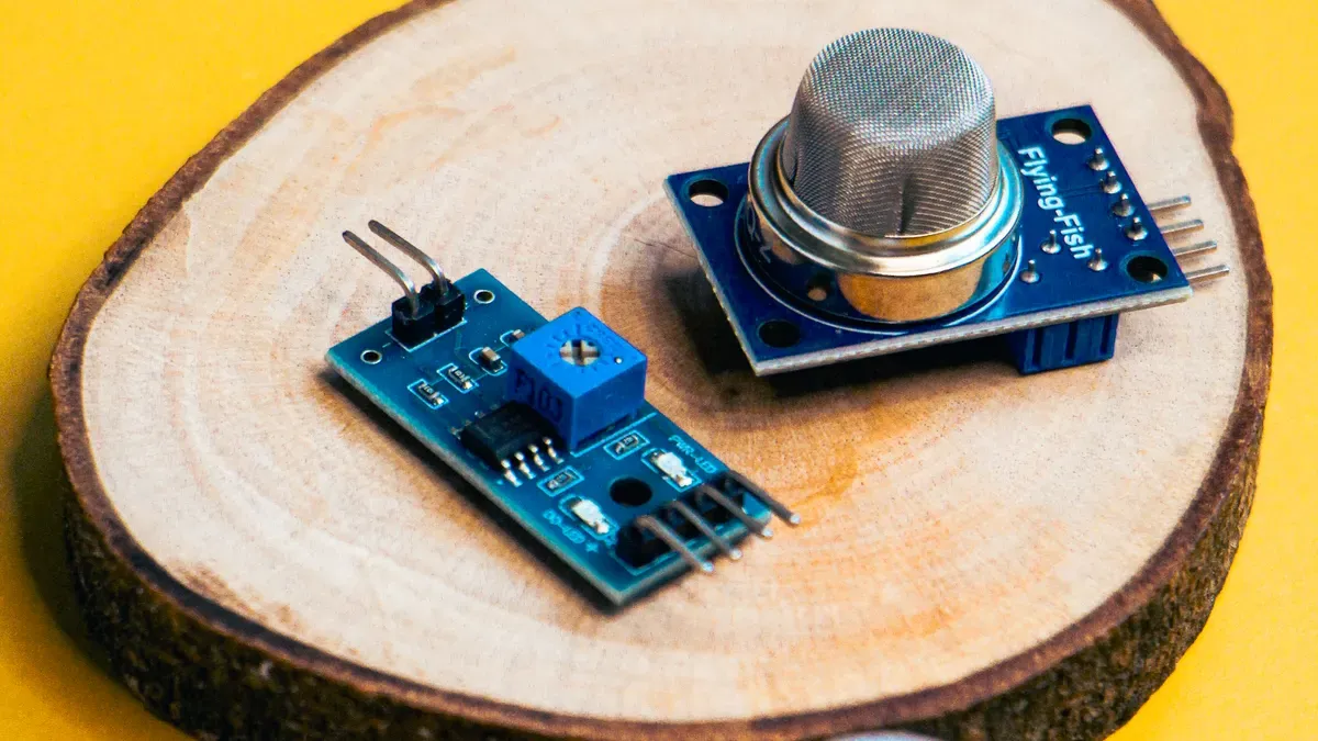
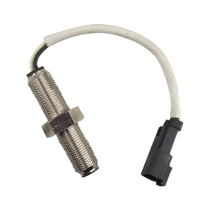
A Magnetic Pickup (MPU) Sensor mounts on a bracket and reads the teeth of a gear on a rotating shaft — often the flywheel ring gear. Clearance is the first item to check when a speed reading fails. The sensor produces its own signal, so a mechanical gap problem looks exactly like an electrical fault at the ECU.
Symptoms of Excessive Gap
A wide air gap weakens the magnetic flux change at the coil. The induced AC voltage falls, and the signal can drop below the detection threshold. Watch for these signs:
- No reading at low RPM, because cranking speed generates the weakest signal
- Signal dropout at high RPM, when the ECU loses the pulse train
- Weak or inconsistent AC voltage on a multimeter
- Tachometer flutter or a needle that jumps
- ECU fault codes for a missing speed signal
The technical support team at Megawatts Parts frequently resolves cases where a no-start fault on a generator set was chased for days. The MPU was new, the wiring tested clean, and the controller was replaced. The real cause was a bracket that had been bent during service. The gap had opened well beyond the specification, and cranking voltage never crossed the threshold. A feeler gauge found the problem in minutes.
Symptoms of Insufficient Gap
A tight gap creates the opposite risk. The tooth can strike the probe as the target expands with heat or as runout varies around the wheel. Look for:
- Intermittent signal that comes and goes with temperature
- Contact marks or a polished spot on the sensor tip
- A damaged pole piece or cracked body
- Metal debris clinging to the magnetic tip
- Early sensor failure, often soon after installation
a construction machine, a technician set the gap at the minimum limit on a cold engine. Once the flywheel ring gear reached operating temperature, the tooth contacted the probe. The tip wore through, the signal failed under load, and the machine derated. The lesson is simple: set the gap with the target in its normal operating position, and respect the upper half of the tolerance band where the manufacturer allows it.
Both failure modes distort the voltage signal in the same way at the ECU — erratic readings, dropouts, or no signal at all. Only a physical gap measurement separates them. That is why experienced technicians reach for a feeler gauge before they reach for a replacement part. A correct air gap on a Magnetic Pickup (MPU) Sensors installation protects both the signal quality and the sensor itself.
Tools and Measurement Techniques
Essential Tools
A feeler gauge is the primary instrument for this job, and both metric and inch sets earn their place in the toolbox. Choose a brass or non-magnetic gauge where possible. A steel blade can disturb the magnetic circuit at the sensor tip and skew a marginal reading.
Supporting tools round out the kit. A depth gauge or dial indicator measures tip depth when the target is hard to reach. A digital multimeter with AC voltage and frequency (Hz) capability confirms signal output. An ohmmeter handles a basic sensor test, and a Gauss meter checks magnet strength on a suspect unit. For advanced work, a signal generator plus oscilloscope lets you test the sensor on the bench before installation.
Set the sensor-to-target air gap using a feeler gauge, following the minimum and maximum gap values specified in the sensor's datasheet. Too large a gap weakens the signal below the detection threshold; too small a gap risks the sensor tip contacting and being damaged by the rotating target.
Measuring the Gap Accurately
Rotate the target until a tooth sits directly under the sensor tip. Insert the feeler gauge between tip and tooth, and confirm a light drag fit — the blade should slide with slight resistance, not force. Repeat the check at multiple points around the wheel to account for runout, and record the minimum and maximum gap.
Manufacturer data anchors the target value. For example, when supplying a Woodward 5430-933 magnetic pickup, Megawatts Parts reminds operators that the recommended air gap is 1.5–2.0 mm (0.060–0.080 in), measured with non-magnetic feeler gauges and adjusted by adding or removing shims or by using the threaded depth stop. Signal output falls off sharply outside this range.
When the target is difficult to reach, measure sensor tip depth relative to the mounting surface with a depth gauge instead. This method is highly recommended on flywheel ring gear installations, where a feeler gauge will not fit cleanly. As a starting point on unfamiliar hardware, position the sensor at roughly 1.5 times its rated sensing range from the target face — a 4 mm gap for a 2.5 mm rated sensor — then verify with a feeler gauge and secure the sensor with a thread-locking L-bracket to hold the set gap.
Step-by-Step Clearance Adjustment
Setting the Gap to Spec
Work with the machine locked out. Disconnect power before any contact with the sensor or target. Clean the sensor tip and the target tooth with a lint-free cloth. Grease, metal dust, and rust scale all distort the reading.
Loosen the mounting clamp or jam nut. Set the gap with the feeler gauge to the manufacturer's specification. Always confirm the spec for the exact sensor and application. Hold the sensor firmly in position and tighten the fastener. Re-check the gap after tightening. The sensor can shift as the clamp draws down, and a gap that was correct a moment ago may now be wrong.
Some pickups use a threaded body with no separate clamp. For these, the counterclockwise method applies. Seat the pickup against the gear, then back it off by turning it counterclockwise 1/4, 1/2, or 3/4 turn. A gap chart for that sensor converts the turn count into a gap distance. After adjusting, check the clearance with a feeler gauge to confirm the result.
Mistakes to Avoid
The golden rule of MPU adjustment is simple: measure against a clean, undamaged tooth, and measure it twice. Setting the gap against a dirty or damaged tooth produces a false reading. The sensor ends up too close to a good tooth, and contact damage follows.
|
Mistake to Avoid |
Why It Matters / Guidance |
|
The gap between sensor and ring gear must be exact; even a fraction of a millimetre shifts signal accuracy. |
|
|
Over-correcting during adjustment |
When tuning stability/gain, over-correction is the most common error — make small changes and let the engine settle between them. |
Two installation points deserve equal attention:
Improper installation or positioning: the sensor must be properly aligned, and the gap must be set correctly. Mounting it too far from or too close to the flywheel can prevent the signal from being detected, a common cause of Code 28 errors.
Over-tightening: excess torque can crack the sensor body. Snug the fastener, then stop.
Set the gap with the target in its normal operating position. Account for runout around the full circumference. Where the manufacturer specifies it, set the gap at operating temperature. Correct clearance on Magnetic Pickup (MPU) Sensors is a measurement, not an estimate.
Verifying the Adjusted Signal

Confirming Voltage Output
Reconnect the pickup after the adjustment. Set the multimeter to AC volts and probe the speed sensor input terminals at the genset controller. Crank the engine or rotate the trigger wheel by hand at the lowest controlling speed. A healthy sensor will generate a fluctuating voltage reading of at least 1.5 VAC during cranking.
Watch the frequency display as speed rises. A passive probe produces an AC voltage whose wave frequency varies with the speed of the monitored device. The moving gear creates a varying flux that induces a voltage in the coil, and the frequency of that voltage is related to the rotational speed. A steady climb in hertz confirms a clean pulse train. A flat or missing reading points to a remaining fault, and further troubleshooting is required.
Final Run Checks
Start the engine and let it idle. Confirm the tachometer holds steady and the ECU reports a stable speed signal. Scan for fault codes and clear any stored history from the earlier failure. A code that returns immediately means the gap or the wiring still needs attention.
Shut down and inspect the sensor tip after a short run. Look for contact marks, a polished spot, or fresh metal debris. Any of these signs means the gap closed up in service. This visual inspection is the quickest diagnostic test — one look at the tip tells you whether the adjustment held. Correct clearance on Magnetic Pickup (MPU) Sensors is confirmed by measurement, voltage, and a visual check together.
Troubleshooting Common Issues
Weak or Missing Signal
Clearance is not always the culprit. A weak 12V battery cranks too slowly to generate a reliable speed signal, and that is the most common cause of all. Damaged flywheel ring gear teeth, a cracked tone ring, or metal debris on the magnetic tip also distort the waveform. So do corroded connectors, backed-out pins, and a sensor with high internal resistance. Always verify battery voltage is healthy and cranking speed is sufficient before attempting to adjust the MPU gap, or you risk chasing a false mechanical fault.
Isolate wiring from sensor failure in four steps. Unplug the pickup and measure AC volts across its two wires while cranking; expect roughly 2–10V AC. A lower reading points to a weak sensor, a poor plug connection, slow cranking, or an incorrect gap. If that test passes, plug the pickup back in and measure at the module connector with the plug removed. A low reading there means the harness or panel is blocking the signal. Reconnect and measure once more; a low reading at this stage suggests a damaged module input. If every check passes, verify the flywheel tooth setting and scan for related alarms.
Gap That Won't Stay Set
A gap that drifts usually has a mechanical cause. Worn mounting hardware lets the bracket move under vibration. A loose clamp backs off over time. Damaged threads prevent the jam nut from holding torque. A sensor of the wrong length bottoms out or sits too far out for the bracket to grip.
The fix follows the cause. Replace worn clamps and fasteners, chase damaged threads with the correct tap, and fit a thread-locking bracket where vibration is severe. Confirm the sensor length against the application before installation.
When a replacement is needed, Megawatts Parts carries aftermarket and genuine generator MPU sensors and engineering machinery sensors built to meet or exceed OEM specifications.
A spare Magnetic Pickup (MPU) Sensors unit on the shelf shortens the next breakdown.
Diagnosis follows a fixed order. Identify the symptoms first. Measure the air gap with a feeler gauge and a depth gauge next. Adjust the sensor to the manufacturer's specification, then verify output with a voltage and run test. A healthy unit holds at least 1.5 VAC during cranking.
Correct clearance separates a reliable speed signal from intermittent failures. One quick re-check after tightening prevents most repeat problems, and that habit pays off on every Magnetic Pickup (MPU) Sensors installation.
FAQ
What is the correct air gap for an MPU sensor?
Always confirm the figure for the exact sensor and application. A Woodward 5430-933 calls for 1.5–2.0 mm (0.060–0.080 in). Measure with a non-magnetic feeler gauge against a clean tooth.
How do I test an MPU sensor with a multimeter?
Unplug the pickup and measure AC volts across its two wires while cranking. Expect roughly 2–10 V AC. A lower reading points to a weak sensor, a poor connection, slow cranking, or an incorrect gap. Reconnect and confirm at least 1.5 VAC during cranking.
Why does my speed signal drop out at high RPM?
A wide air gap is the usual cause. The magnetic flux change weakens, and the induced voltage falls below the detection threshold as speed rises. Check the gap around the full circumference of the flywheel ring gear, since runout can open the clearance at one point.
Can I set the gap by turning the sensor instead of using a feeler gauge?
Yes, on threaded-body pickups with no separate clamp. Seat the pickup against the gear, then back it off counterclockwise 1/4, 1/2, or 3/4 turn. A gap chart for that sensor converts the turn count into a distance. Confirm the result with a feeler gauge afterward.
How often should I check speed sensor clearance?
Check the air gap at every service interval and after any work near the bracket or flywheel housing. Best practice dictates re-checking the gap after tightening the fastener, because the sensor can shift as the clamp draws down. Megawatts Parts highly recommends this single habit to prevent most repeat failures.

Read More
-
 BLOG
 Megawatts BlogTier 4 Final & Common Rail Systems: Why Micro-Contamination Destroys Modern Diesel InjectorsMicro-contamination destroys modern diesel injectors because Tier 4 Final common rail systems run at extreme pressure with micron-level tolerances. Debris that bypasses filtration scores precision com...
-
 BLOG
Megawatts BlogJIT Inventory vs. Safety Stock: Balancing Capital and Risk in Generator MaintenanceThe right approach is a deliberate, risk-based balance between JIT inventory and safety stock, not a pure companywide choice. Can you afford to tie up cash in every spare part, or risk a costly outage...
-
 BLOG
Megawatts BlogTotal Cost of Ownership (TCO) in Fleet Maintenance: Hidden Logistics Costs of Sourcing Multiple OEMsWhat hidden logistics costs emerge when sourcing multiple OEMs? How heavily do they weigh on Total Cost of Ownership (TCO) in Fleet Maintenance? A fleet manager compares two identical parts at differe...
-
 BLOG
Megawatts BlogAnatomy of a Breakdown: Warning Signs Your Engine Driven Water Pump is Failing Before It LeaksAn engine-driven water pump typically broadcasts failure well before it drips. The pre-leak danger window is that brief period when noise, odor, temperature swings, or residue appear but no puddle for...

Subscribe to enjoy 10% off
Stay informed about new products and sales

-
INFORMATION
Contact Us
-
CHINA SALES OFFICE: No. 2-11, No. 8, Gaotai Road, Gaishan Investment Zone, Cangshan District, Fuzhou, Fujian
-
SAUDI ARABIA FACTORY: 7264 Shakra, Al Faisaliyyah, REFB3035, 3035, Riyadh 12883
-
COLOMBIA SALES OFFICE: 92-32 26th Street, 03-118, Bogota
-
NIGERIA FACTORY: Plot 5 Chivita Avenue Ajao Estate Isolo Lagos
-
Email:sales@megawattsparts.com
Follow Us


Copyright © 2025 Megawatts All Rights Reserved.



Select Previous Button or Search Directly on Search Bar!
Shop All
 English
Currency: <{ pagedata.current_currency }>(<{ pagedata.current_currency_code }>)
Are you in the right place?

You agree to MegaWatts.com's Terms of Use and Privacy Policy by subscribing. You may receive emails with useful tips, promotions, and offerings.
No, thanks. I'd rather pay full price.