


Generator Control Panel Failures: How to Test and Replace Faulty Relays
by Megawatts - Updated At 2026-07-02
Generator control panel relay failures can instantly halt operations and disrupt critical industrial systems. When these control relays malfunction, facilities face the immediate risk of unexpected downtime and costly operational delays. Swift diagnosis and the integration of reliable replacement parts are essential to keep generator control panels operating at peak performance. Megawatts Parts stands out as a trusted source for heavy-duty generator set parts, delivering quality components with fast shipping and responsive technical support. Consistent maintenance protocols and the selection of high-quality relays prevent future failures, protecting industrial generators from avoidable power interruptions.
Generator Control Panel Relay Troubleshooting

Common Relay Failure Symptoms
Generator control panel faults frequently disrupt industrial operations. During the troubleshooting of common faults in electrical control panels, specific symptoms often point directly to relay issues. The panel interface may become unresponsive, or the system may experience noticeable delays in executing start and stop commands. In some instances, alarms trigger without an underlying cause, and inconsistent readings appear on the display. Left unresolved, these faults can cascade into severe power supply interruptions and broader component failures. The table below summarizes the most frequently reported symptoms:
|
Symptoms of Faulty Relays in Generator Control Panels |
|
Panel interface becomes unresponsive |
|
Delays in start/stop commands |
|
Incorrect reporting of generator data |
|
Alarms triggering without cause |
|
Inconsistent readings on the panel |
|
Failure to detect overloads or overheating |
Recognizing these early warning signs is critical to preventing cascading faults and minimizing costly downtime. Skilled troubleshooting enables maintenance teams to isolate common faults in electrical control panels before they escalate into systemic failures.
When diagnosing these symptoms, it is crucial to differentiate between panel logic failures and downstream hardware issues. If a relay tests normal but start/stop failures persist, technicians should verify the execution components by referencing our field guide on stop solenoid wiring and testing. Similarly, if the panel displays erratic warnings instead of genuine faults, you can quickly isolate the root cause using the 5-minute sensor test to diagnose a false high-temperature alarm.
Causes of Relay Malfunction
Environmental conditions play a critical role in the reliability of electrical control panels. High humidity can cause moisture ingress, leading to corrosion and electrical shorts. Elevated temperatures compromise the thermal stability of electronic components, resulting in faults and operational errors. Wiring and connection problems also contribute to relay failures. Protecting industrial generators from these environmental factors ensures consistent performance. Regular inspections for signs of component failures and the prompt troubleshooting of common faults are essential to maintain system integrity.
Electrical and electronic equipment must be protected from adverse environmental effects, including high temperature and humidity:
- High humidity leads to corrosion and electrical shorts.
- Elevated temperatures cause operational errors and failures.
- Wiring and connection problems increase the risk of faults.
When reliable replacement relays are required, Megawatts Parts offers high-quality solutions for generator control panels.
Safety Precautions for Electrical Control Panels
Safety remains your top priority when troubleshooting faults in generator systems. Follow OSHA and NFPA guidelines to protect yourself and others. Maintain proper clearance around the generator, and ensure emergency stop switches are accessible. Always wear appropriate personal protective equipment, including insulated gloves, safety goggles, and arc-rated clothing. Lockout/tagout procedures prevent accidental energization during maintenance.
|
Aspect |
Requirement |
|
Clearance Requirements |
Minimum three feet at the front and sides of the generator for access (NFPA 110). |
|
|
Five feet clearance from openings and combustible walls (NFPA 37). |
|
Safety Features |
Emergency stop switches at entrances and within line of sight. |
|
|
Spill containment and fire-rated barriers for fuel systems. |
|
Training Protocols |
Lockout/tagout training per OSHA is mandatory. |
|
Emergency Protocols |
Staff must know how to activate emergency stop functions and notify responders. |
Tip: Technicians must always verify the correct PPE is equipped before initiating any troubleshooting procedures. Regular inspection and strict adherence to safety standards reduce risks and ensure the reliable operation of electrical control panels within generator systems.
For systems experiencing frequent faults or issues, exploring the relay and controller categories at Megawatts Parts provides dependable, long-term solutions.
Step-by-Step Troubleshooting Process
A methodical troubleshooting approach enables technicians to diagnose relay issues in generator control panels efficiently. Following a structured process reduces downtime and prevents unnecessary part replacements. This systematic method also enhances maintenance documentation for future reference, ensuring quicker and more accurate repairs.
Tools Needed for Testing
Testing key control components safely and accurately requires the proper equipment. All diagnostic tools must meet industry safety ratings and certifications. The following list covers essential tools and their relevant standards:
- Insulated screwdrivers and pliers (UL 508, CSA C22.2)
- Multimeter with relay testing capability (IEC 61810-1)
- Clamp meter for current measurement
- Portable insulation resistance tester
- Personal protective equipment (PPE): gloves, goggles, arc-rated clothing
Tip: Technicians must always verify the incoming power supply before initiating any troubleshooting. It is crucial to confirm that all testing instruments are rated for the specific voltage and current levels present within the generator control panel.
Visual and Manual Inspection
You begin troubleshooting by visually inspecting the relay and surrounding components. Look for signs of overheating, corrosion, or physical damage. You inspect wiring and connections for loose terminals, frayed wires, or discoloration. Use the table below to standardize your manual inspection techniques:
|
Maintenance Procedure |
Description |
|
Conduct regular checks during preventive maintenance to ensure proper operation. |
|
|
Calibration checks |
Perform checks as outlined in the generator's technical manual to maintain accuracy. |
|
Module swap capability |
Replace modules quickly in the field without specialized tools. |
|
System diagnostics |
Use fault codes or indicator lights to assist in troubleshooting issues. |
Practical Example: If a relay displays burn marks and a melted casing, it indicates a risk scenario where severe overheating has compromised the component. Technicians must immediately disconnect the power supply and replace the relay to prevent further system damage.
Note: Always consult the generator's system documentation before performing manual inspections. This ensures strict adherence to manufacturer guidelines and prevents common diagnostic mistakes.
Multimeter Testing Procedures
A multimeter is used to test basic relay functionality, such as coil integrity and contact continuity, to confirm a diagnosis. Follow these steps for accurate results:
- Set the multimeter to the ohms (Ω) setting to measure the coil resistance, comparing the result against the manufacturer's specified range.
- Test for contact continuity by verifying an open circuit (infinite resistance) across Normally Open (NO) contacts and a closed circuit (near zero resistance) across Normally Closed (NC) contacts while the relay is de-energized.
- Safely apply the rated control voltage to the coil and listen for an audible activation click, then re-test the contacts to confirm they transition states correctly.
- Document all measured resistance values and voltage readings for maintenance records and future reference.
Practical Example: A technician sets a multimeter to measure resistance across the relay coil. If the reading displays an open circuit (infinite ohms), it confirms a failed internal coil. The relay must be replaced and the circuit retested to verify proper operation.
Alert: Never bypass safety protocols during testing. Technicians must always isolate current transformer (CT) secondary circuits, measure insulation resistance, and confirm polarities before proceeding with functional relay testing.
Following this step-by-step troubleshooting process minimizes risks and avoids costly facility downtime. It ensures that key control components are tested thoroughly and the incoming power supply is verified before any component replacements are made. For complex electrical faults that extend beyond basic relays, facilities may require advanced logic units, such as the Caterpillar Electronic Control Module for CAT 3516B/3508B, to fully restore system integrity.

Replacing Faulty Relays in Electrical Control Panels

Preparation and Safety Steps
The generator and electrical control panels must be prepared carefully before initiating any relay replacement. Technicians must begin by disconnecting all power sources, including the generator starting battery—removing the negative terminal first and reconnecting it last. Power at the main transfer switch must be turned off and automatic start functions completely disabled. The system must be secured using standard Lockout/Tagout (LOTO) procedures, including a clear "Do Not Operate" tag. Personnel must exclusively use certified insulated tools and operate on dry, insulated surfaces. Adequate ventilation must be ensured within the generator plant room or canopy. Engine components must be allowed to cool down fully prior to maintenance. Batteries and fuel systems require careful handling with mandatory eye and hand protection. Auxiliary or utility power connections must be locked out to prevent accidental energization. A fire extinguisher rated for electrical fires must remain accessible at all times. Furthermore, technicians must never work alone on high-voltage industrial systems; standby personnel must be present to assist in the event of an emergency.
Warning: Bypassing these isolation steps exposes personnel to severe electrical shock, fire hazards, and catastrophic equipment damage. Strict adherence to safety protocols is mandatory to protect both technicians and critical facility infrastructure.
Removing and Installing Relays
Once the faulty relay is identified within the electrical control panel using prior inspection and testing results, technicians can proceed with the removal process. All wiring connections must be carefully loosened and removed, with their exact positions documented or labeled to ensure accurate reinstallation. The component should then be carefully extracted from its socket or mounting bracket. The relay base and the surrounding enclosure area must be thoroughly inspected for corrosion or moisture ingress, and the terminal contacts cleaned if necessary.
During installation, it is critical to verify that the new relay strictly matches the OEM voltage and current specifications required for the generator system. All wiring connections must be secured and torqued tightly to prevent future high-resistance faults or loosening caused by engine vibration. Utilizing high-quality, industrial-grade generator relays from trusted suppliers ensures reliable long-term operation and minimizes future maintenance cycles.
Tip: Double-check wiring diagrams and system documentation before reconnecting any wires. This step prevents common errors and ensures safe operation.
Post-Replacement Testing
After installing the new relay, restore power to the electrical control panels. Reset the system and check all breakers and fuses. Confirm battery and ground connections. Test the generator by running a start-up sequence and monitoring for proper relay function. Watch for any abnormal alarms or delays. Most post-replacement failures result from battery issues, fuel supply problems, or air in the fuel system. Address these issues promptly to avoid further downtime. Document your work for future troubleshooting and maintenance.
If the diagnosis points to a broader logic failure rather than a single electromechanical fault, explore the comprehensive range of generator controllers at Megawatts Parts for dependable system upgrades.
Preventive Maintenance for Generator Control Panels

Inspection and Cleaning Tips
Protecting generator control panels from unexpected faults requires a consistent inspection and cleaning routine. Maintenance teams should initiate weekly visual checks to identify physical damage, loose connections, or dust accumulation. Monthly cleaning utilizing an ESD-safe vacuum or soft brush effectively removes debris without compromising sensitive electronic components. Technicians must routinely check for corrosion and inspect electrical control panels for early signs of wear. Calibrating meters and sensors quarterly maintains system accuracy, while regular battery system tests confirm proper charging voltage and overall condition. Executing these steps ensures faults are caught early and troubleshooting remains highly efficient.
Tip: Technicians must strictly use non-abrasive cleaning tools to avoid damaging delicate relay contacts or internal wiring.
Tightening Connections and Preventing Moisture
Failures in generator control panels can be significantly reduced by systematically verifying and tightening all electrical connections during each scheduled maintenance session. Upgrading to silver-plated copper terminals provides superior resistance to oxidation. Applying torque-controlled tightening is essential to prevent high-resistance connection failures. Utilizing spring washers and industrial thread-locking adhesives on bolts effectively prevents loosening caused by heavy engine vibration. Furthermore, sealing cable entries with industrial rubber gaskets and metal compression nuts, alongside installing self-sealing grommets, blocks water and moisture from penetrating the electrical control panels. These preventive actions eliminate faults driven by loose contacts and moisture ingress.
Note: Moisture ingress and high-frequency vibration remain the leading causes of electromechanical faults in heavy-duty generator systems. Proactively addressing these environmental risks is vital to extending equipment lifespan.
Scheduling Regular Maintenance
Minimizing faults and avoiding emergency repairs necessitates scheduling rigorous preventive maintenance for generator control panels. The control panel and main transfer switch must be inspected at manufacturer-specified intervals to guarantee reliable operation during utility outages. A comprehensive preventive maintenance plan should integrate mechanical engine checks, fluid analysis, battery load testing, and exhaustive control system reviews. Regular, structured servicing allows technicians to identify minor anomalies before they escalate into catastrophic failures. This proactive approach ensures strict compliance with industrial safety regulations and maximizes the generator's operational lifespan. Megawatts Parts supports these long-term reliability goals by supplying premium, OEM-grade components for every maintenance cycle.
Callout: Preventive maintenance remains the most effective defense against unexpected faults and costly facility downtime. Integrating reliable parts from Megawatts Parts ensures that generator control panels are fully prepared for any operational challenge.
Strict adherence to safety protocols and comprehensive maintenance schedules protects critical infrastructure, ensuring industrial generators remain on standby for emergency deployment. For dependable replacement components and responsive technical support, Megawatts Parts is the premier choice.
If internal maintenance teams lack the specific expertise required for complex control panel diagnostics, contacting a certified industrial generator technician for field guidance is highly recommended.
FAQ
How can a failed relay in a generator control panel be identified?
Unresponsive controls, false alarms, or inconsistent readings are primary indicators. If the generator fails to execute start or stop commands as expected, a faulty relay is a likely cause. Regular system inspections facilitate the early detection of these electromechanical issues.
What tools are required for relay troubleshooting?
Technicians require insulated screwdrivers, a multimeter with relay testing capabilities, and appropriate personal protective equipment (PPE). It is imperative that all diagnostic tools meet industry safety standards and are rated for the specific panel voltages.
Can relay replacement be performed without professional field assistance?
Relay replacement should only be conducted by trained personnel strictly adhering to OEM guidelines and lockout/tagout (LOTO) safety protocols. For complex panel configurations, consulting a certified industrial technician is highly recommended. Utilizing high-quality components from Megawatts Parts ensures reliable system restoration.
What is the recommended preventive maintenance schedule for generator control panels?
Generator control panels require weekly visual inspections and monthly cleaning to remove debris. Electrical connections should be verified and checked for moisture ingress on a monthly basis. A comprehensive preventive maintenance review must be scheduled quarterly to ensure long-term reliability and minimize facility downtime.

Read More
-
 BLOG
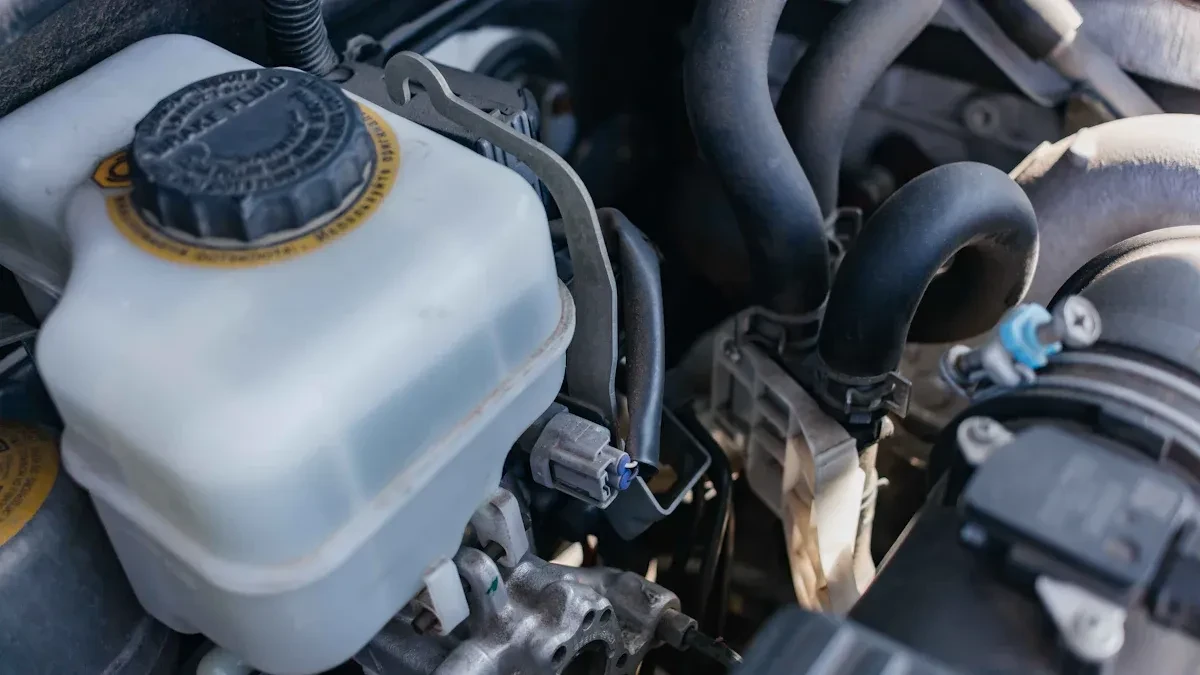
BLOG Megawatts BlogEngine Oil Cooler Leaks: Why There is Oil in Your Generator's CoolantOil in coolant is a warning sign that engineers cannot ignore. An engine oil cooler leak is the most frequent cause, but other failures can also lead to oil mixing with coolant. The "pulp orange" phen...
 -
 BLOG
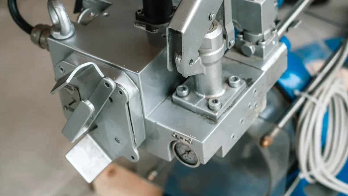
Megawatts BlogGenerator hunting and surging: Troubleshooting speed sensors and electronic actuatorsGenerator hunting and surging often result from issues with speed sensors or electronic actuators. These problems can cause the generator to fluctuate in speed or output, leading to unstable operation...
BLOG
Megawatts BlogGenerator hunting and surging: Troubleshooting speed sensors and electronic actuatorsGenerator hunting and surging often result from issues with speed sensors or electronic actuators. These problems can cause the generator to fluctuate in speed or output, leading to unstable operation... -
 BLOG
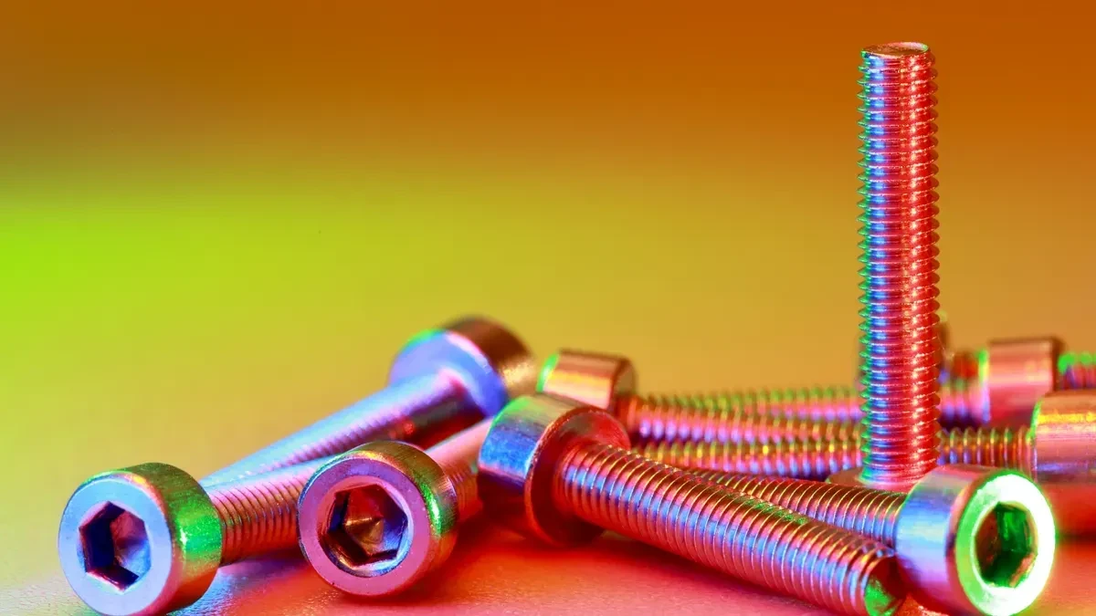
Megawatts BlogThe Danger of Reusing Hardware: Why New Fasteners Are Critical for Cylinder Head RebuildsA successful engine rebuild hinges on one crucial detail: precise clamping force. Reusing old cylinder head fasteners—especially stretched bolts and deformed washers—is a direct ticket to...
BLOG
Megawatts BlogThe Danger of Reusing Hardware: Why New Fasteners Are Critical for Cylinder Head RebuildsA successful engine rebuild hinges on one crucial detail: precise clamping force. Reusing old cylinder head fasteners—especially stretched bolts and deformed washers—is a direct ticket to...

Subscribe to enjoy 10% off
Stay informed about new products and sales

-
INFORMATION
Contact Us
-
CHINA SALES OFFICE: No. 2-11, No. 8, Gaotai Road, Gaishan Investment Zone, Cangshan District, Fuzhou, Fujian
-
SAUDI ARABIA FACTORY: 7264 Shakra, Al Faisaliyyah, REFB3035, 3035, Riyadh 12883
-
COLOMBIA SALES OFFICE: 92-32 26th Street, 03-118, Bogota
-
NIGERIA FACTORY: Plot 5 Chivita Avenue Ajao Estate Isolo Lagos
-
Email:sales@megawattsparts.com
Follow Us


Copyright © 2025 Megawatts All Rights Reserved.
Select Previous Button or Search Directly on Search Bar!
Shop All
 English
Currency: <{ pagedata.current_currency }>(<{ pagedata.current_currency_code }>)
Are you in the right place?

You agree to MegaWatts.com's Terms of Use and Privacy Policy by subscribing. You may receive emails with useful tips, promotions, and offerings.
No, thanks. I'd rather pay full price.