


Stop Solenoid Wiring and Testing: A Field Guide for Heavy Machinery
by Megawatts - Updated At 2026-06-25
When heavy machinery refuses to shut down, a faulty stop solenoid is usually the culprit—creating immediate safety hazards and risking severe engine damage. Whether you are troubleshooting a runaway diesel engine or wiring a replacement, mastering these diagnostic steps is non-negotiable for field technicians. This guide breaks down the exact wiring and testing procedures you need to quickly isolate faults and restore reliable operation with premium components from Megawatts Parts.
Stop Solenoid Basics
What Is a Stop Solenoid
A stop solenoid is an electromechanical device that plays a central role in engine control for heavy machinery. The fuel stop solenoid manages the flow of fuel to the engine. When the operator initiates shutdown, the stop solenoid activates, moving a plunger to block the fuel passage. This action cuts off the fuel supply, resulting in immediate engine shutdown. The fuel shut-off solenoid is essential for both diesel and gasoline engines, providing a reliable method to halt engine operation during routine maintenance or emergencies. Experienced engineers emphasize that a properly functioning fuel stop solenoid prevents engine damage and ensures safety. In cases where the engine refuses to stop, technicians typically trace the issue to faulty wiring or a burnt coil. For a deeper dive into this specific symptom, explore our comprehensive guide on why your generator won't shut down.
How It Works in Heavy Machinery
Heavy machinery relies on precise engine control to operate safely and efficiently. The fuel stop solenoid integrates with the engine control system, responding to electrical signals from the operator or automated controls. If the physical wiring is intact but no signal is sent, the issue often traces back to a malfunctioning controller failing to trigger the shutdown logic. When activated, the fuel stop solenoid closes the fuel line, stopping the engine instantly. This process is critical for solenoid valve testing and heavy machinery electrical troubleshooting. Operators must follow the stop solenoid wiring diagram to ensure correct installation. Stop solenoid testing is a routine procedure, helping identify issues before they lead to operational failures. Technical consultants recommend regular inspection of the fuel shut-off solenoid to avoid unexpected shutdowns or failures.
Megawatts Product Features
The Megawatts Stop Solenoid stands out for its advanced engineering and robust performance. It is designed for compatibility with a wide range of engine models, making it a versatile solution for operators and mechanics. The fuel stop solenoid from Megawatts features a fail-safe, normally closed design, ensuring that the engine shuts down reliably when required. Dual-power mode delivers up to 90% energy savings compared to standard solenoids. The response time is rapid, opening in less than 50 milliseconds. Durable materials such as ductile iron and stainless steel enhance longevity. Double sealing rings reduce leakage rates to less than 0.01%. Maintenance cycles extend beyond two years, minimizing downtime and replacement costs. The table below highlights key differences between Megawatts and standard solenoids:
|
Feature |
Megawatts Stop Solenoid |
Standard Stop Solenoid |
|
Design |
Fail-safe normally closed |
Standard design |
|
Energy Efficiency |
Dual-power mode, 90% savings |
Full-power operation |
|
Response Time |
≤50 ms |
Slower response |
|
Material |
Ductile iron/stainless steel |
Varies |
|
Sealing |
Double sealing rings, ≤0.01% |
Standard sealing |
|
Maintenance |
>2 years cycle |
Annual inspections required |
Tip: Always consult the stop solenoid wiring diagram and perform stop solenoid testing before installation. This ensures proper engine control and prevents fuel stop solenoid failures.
Tools and Safety

Required Tools for Wiring and Testing
Proper stop solenoid wiring and testing require a set of essential tools and a systematic approach. Technicians working on heavy machinery should prepare the following items before beginning any solenoid valve testing or stop solenoid wiring and testing procedures:
- Multimeter – For electrical continuity and voltage checks during stop solenoid testing.
- Wrenches and Socket Set – To disconnect and secure hydraulic lines and mounting bolts.
- Screwdrivers – For removing electrical connectors and terminal covers.
- Penetrating Oil – Useful for loosening corroded or stuck components.
- Clean Container – To collect hydraulic fluid and prevent contamination.
- Shop Towels – For cleaning the area around the fuel shut-off solenoid.
- Replacement Stop Solenoid – Ensure compatibility with your engine model, such as the Megawatts Stop Solenoid.
- Protective Gloves and Safety Glasses – For personal protection during heavy machinery electrical troubleshooting.
- Stop Solenoid Wiring Diagram – Reference for accurate connections.
- 12V Battery (if bench testing) – For off-machine solenoid function checks.
Tip: Always inspect and clean the mounting area before installing a new solenoid. This prevents debris from entering the hydraulic or fuel system and ensures a secure fit.
Safety Precautions
Safety remains the top priority during stop solenoid wiring and testing. Experienced engineers recommend the following precautions to minimize risk:
- Depressurize the System: Allow hydraulic or fuel systems to fully depressurize before disconnecting any lines. This step prevents accidental fluid spray and potential injury.
- Disconnect Power: Always disconnect the battery or power source before handling electrical connections. This reduces the risk of electric shock or short circuits.
- Wear PPE: Use gloves and safety glasses to protect against fluid leaks and electrical hazards.
- Check for Leaks: After installation, test the system for leaks and verify all connections are tight.
- Follow Manufacturer Guidelines: Reference the stop solenoid wiring diagram and product manual for your specific model. This ensures correct installation and reliable operation.
If a diesel engine won't shut off or exhibits erratic shutdown behavior, stop solenoid testing and heavy machinery electrical troubleshooting should be performed immediately. Prompt action can prevent costly engine damage and downtime.
Wiring Guide

Identifying Terminals and Wires
Technicians must begin by identifying the correct terminals and wires before installing a stop solenoid. The 3-wire fuel shut-off solenoid typically features three distinct connections designed for heavy-duty operation: the Pull coil, the Hold coil, and Ground. Each wire serves a critical physical function in the control circuit. The Pull coil draws a momentary high current during engine cranking to overcome heavy spring tension and open the fuel valve. Once the engine is running, the Hold coil takes over, using a continuous low current to keep the valve open without overheating. Ground simply completes the electrical circuit.
Reference the stop solenoid wiring diagram provided by the manufacturer. This diagram outlines the color codes and terminal positions for the 3 wire fuel shut-off solenoid. In most heavy machinery, the wiring harness will include labeled connectors. If labels are missing, use a multimeter to trace continuity and confirm each wire’s purpose. Experienced engineers recommend marking wires with tags or tape to prevent confusion during reassembly.
Tip: Always photograph the original wiring setup before disconnecting any components. This visual reference can prevent errors during installation.
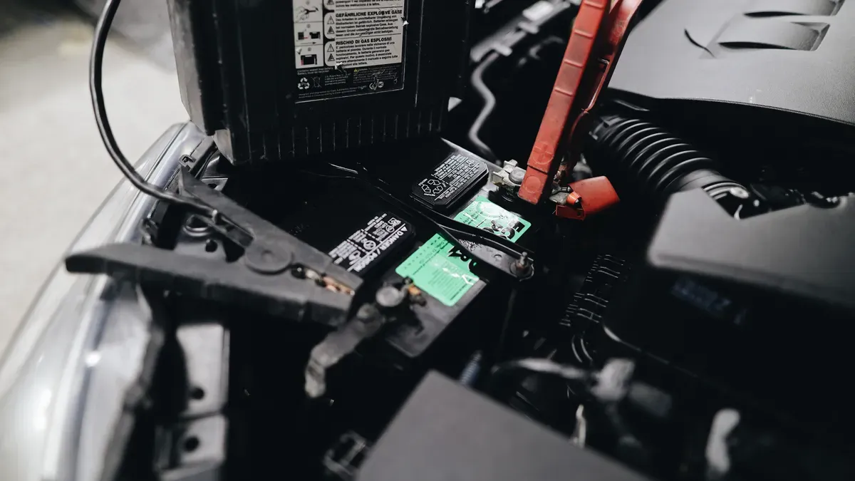
Disconnecting Power Safely
Safety is paramount during stop solenoid wiring and testing. Begin by shutting down the engine and allowing all moving parts to come to a complete stop. Locate the main battery disconnect switch or remove the negative battery cable. This step eliminates the risk of accidental short circuits or electric shock.
Inspect the area around the stop solenoid for residual voltage using a multimeter. Confirm that no power remains in the circuit. In high-pressure fuel systems, depressurize the lines according to the manufacturer’s guidelines. Wear protective gloves and safety glasses to guard against unexpected leaks or electrical hazards.
Alert: Never attempt to disconnect or wire a 3 wire fuel shut-off solenoid with the battery connected. Even a brief surge can damage sensitive electronics or cause personal injury.
Connecting the Megawatts Stop Solenoid
The Megawatts stop solenoid is engineered for straightforward installation. Position the solenoid in its mounting bracket, aligning it with the fuel control linkage. Secure the unit with the appropriate bolts, tightening to the specified torque.
Connect the wiring harness to the 3 wire fuel shut-off solenoid. When installing, attach the high-current Pull wire to the starter relay terminal, the low-current Hold wire to the ignition switch, and secure the Ground wire to the engine block. Use the stop solenoid wiring diagram to verify each connection. For best results, crimp or solder terminals to ensure a solid electrical bond. Apply dielectric grease to prevent corrosion at the connectors.
If the machine uses a relay or fuse in the circuit, inspect them closely. A burnt-out or sticking contact often mimics a coil failure, so replacing it with a heavy-duty relay is a fast, inexpensive way to ensure stable power delivery before proceeding. This step can reveal issues such as weak actuation or internal shorts.
Note: The Megawatts stop solenoid is compatible with standard solenoid valve testing procedures. Always check power and wire connections before energizing the system.
Final Checks
After wiring the stop solenoid, conduct a thorough inspection. Confirm that all terminals are tight and free from corrosion. Route wires away from hot surfaces and moving parts to prevent abrasion or heat damage. Secure the harness with cable ties or clamps.
Restore battery power and initiate stop solenoid testing. Activate the engine shutdown control and listen for a distinct click from the solenoid. This audible response indicates proper actuation. Use a multimeter to measure voltage at the solenoid terminals during operation. The reading should match the manufacturer’s specifications.
If the diesel engine won't shut off or the solenoid fails to respond, revisit the stop solenoid wiring diagram and repeat the heavy machinery electrical troubleshooting steps. Common issues include reversed wires, poor ground connections, or damaged harnesses. Address these problems promptly to avoid operational delays.
Tip from Technical Consultants: Document each wiring change and test result in a maintenance log. This practice supports future diagnostics and ensures compliance with safety standards.
A properly installed stop solenoid guarantees reliable engine shutdown and protects critical components. Routine solenoid valve testing and adherence to wiring best practices extend the service life of both the solenoid and the engine.
Stop Solenoid Testing
Visual Inspection Steps
Visual inspection forms the foundation of effective stop solenoid testing. Begin by examining the stop solenoid and its immediate environment. Look for signs of corrosion, loose connections, or damaged insulation on the wiring harness. A properly installed stop solenoid should display certain visual indicators that confirm correct installation and energization. Many modern heavy machinery systems use lighted connector kits. These kits feature a 24V DC integrated indicator light, which illuminates when the solenoid receives power. This visual cue helps technicians quickly identify whether the stop solenoid is energized during operation.
|
Feature |
Description |
|
Lighted Connector Kits |
24V DC integrated indicator light showing solenoid energization |
Inspect the mounting bracket and ensure the stop solenoid sits securely without excessive vibration. Check that all fasteners are tight and that the fuel shut-off solenoid linkage moves freely. If the indicator light fails to illuminate or if you notice any physical damage, further stop solenoid testing is required. Always reference the stop solenoid wiring diagram to confirm that all wires connect to their designated terminals.
Tip: Experienced engineers recommend inspecting the area for fuel leaks or residue, which may indicate improper sealing or a failing solenoid.
Electrical Testing with Multimeter
Electrical testing with a multimeter is a critical step to verify the integrity of the dual coils and confirm that the unit receives the correct power.
Begin by setting the multimeter to measure resistance (ohms). Since heavy-duty solenoids contain two separate circuits, you must test both:
- Pull Coil Resistance: Probe between the Pull terminal and Ground. Because it requires high current, a healthy coil should read very low, typically between 0.5 to 2.5 ohms.
- Hold Coil Resistance: Probe between the Hold terminal and Ground. This should read higher, generally between 10 to 40 ohms.
Any reading showing infinite resistance (OL) indicates a broken internal wire, requiring an immediate replacement.
Next, switch the multimeter to DC voltage mode. Reconnect the wiring harness and turn the ignition key to the "ON" position (without cranking). Measure the voltage across the Hold terminal and Ground. The expected voltage must closely match your system's battery voltage (e.g., 11.5V+ for a 12V system, or 23.5V+ for a 24V system).
|
Parameter |
Expected Value |
|
Pull Coil Resistance |
0.5 - 2.5 ohms |
|
Hold Coil Resistance |
10 - 40 ohms |
|
Operating Voltage |
Near battery voltage (12V or 24V) |
Readings drastically lower than your battery voltage do not indicate a failed solenoid, but rather suggest severe wiring corrosion, a blown fuse, or a failing relay in the power supply chain.
Bench Testing with a 12V Battery
Bench testing allows technicians to evaluate the stop solenoid outside the machinery. This method is especially useful when the diesel engine won't shut off or when in-field diagnostics are inconclusive. Follow these steps:
- Remove the stop solenoid from the machinery.
- Connect jumper cables to a reliable 12V battery.
- Apply power directly to the solenoid
Observe the plunger and gear movement. If the plunger does not move, the solenoid may be faulty.
Bench testing provides a clear indication of solenoid function without interference from other system components. Always consult the stop solenoid wiring diagram to ensure correct polarity during this process.
Checking for Audible Click
The audible click test is a simple yet effective method in stop solenoid testing. When the stop solenoid receives power, it should emit a distinct clicking sound. This sound indicates that the internal mechanism is engaging and the plunger is moving as designed.
- An audible click from the stop solenoid confirms proper function and engagement.
- The absence of a click may signal a malfunction, such as a stuck plunger, failed coil, or wiring issue.
If you do not hear a click during stop solenoid testing, revisit the wiring connections and repeat the electrical tests. In some cases, a faulty relay or blown fuse may prevent the solenoid from energizing. Technical consultants advise using both the audible click and multimeter tests to confirm the health of the stop solenoid.
Tip: Always document your stop solenoid testing results and any corrective actions in the maintenance log. This practice supports future diagnostics and ensures compliance with safety protocols.
A thorough approach to stop solenoid testing—combining visual inspection, electrical measurement, and functional checks—ensures reliable engine shutdown and extends the service life of both the solenoid and the engine. Regular testing, adherence to the stop solenoid wiring diagram, and prompt troubleshooting help prevent unexpected failures in heavy machinery.
Troubleshooting Issues
Common Failure Symptoms
Heavy machinery operators often encounter issues with the stop solenoid that disrupt the fuel supply system. Recognizing early warning signs helps prevent costly downtime and engine damage. Typical symptoms include:
- Sudden engine shutdown, often caused by abrupt interruption of the fuel supply system.
- Difficulty starting the engine, especially during cold weather.
- Engine stalling or intermittent loss of power while running.
- Unsteady idling, with the engine revving unpredictably.
- Unusual noises, such as clicking or rushing sounds near the solenoid.
- Excessive smoke from the exhaust, indicating improper combustion.
- Poor acceleration and sluggish performance.
- Visible fuel leakage around the solenoid area.
- Valve not opening or closing, resulting in start failures or wasted fuel.
Experienced engineers recommend that operators check the fuel supply system immediately when these symptoms appear. Early detection and stop solenoid testing reduce the risk of engine failure.
Diagnosing Wiring Problems
Accurate diagnosis of wiring issues is essential for reliable stop solenoid operation. Technicians follow a systematic approach:
- Perform Lockout/Tagout on the electrical supply and bleed hydraulic pressure. Inspect for oil leaks, bent tubes, loose bolts, and verify voltage rating.
- Re-energize the control circuit, toggle the solenoid switch, and check for magnetic attraction using a screwdriver.
- Use a multimeter to check supply voltage under load and measure coil resistance.
- Test the manual override button to determine if the hydraulic path is clear or if the spool is seized.
Technical consultants advise referencing the stop solenoid wiring diagram during each diagnostic step. Heavy machinery electrical troubleshooting often reveals wiring faults that cause a malfunctioning solenoid.
When to Replace the Solenoid
Replacement decisions depend on the solenoid’s condition and application. Operators should consider the following:
- Evaluate the size and application of the solenoid valve. Replacement may be more cost-effective than repair for standard units.
- Assess the system design. Complex or custom-built valves may warrant repair to avoid high replacement costs.
- Repair rubber parts and springs if damaged. Replace the solenoid if other components show significant wear.
Routine stop solenoid wiring and testing help determine when replacement is necessary. If diagnostic tests confirm a failed coil or seized plunger, immediate replacement is mandatory. Choosing an OEM-grade stop solenoid guarantees a fail-safe, normally closed design that permanently secures your equipment's shutdown sequence.
Tip: Maintain a detailed maintenance log to track solenoid performance and replacement history. This practice supports future diagnostics and compliance.
Maintenance Tips
Routine Inspection
Routine inspection forms the backbone of reliable stop solenoid operation. Technicians should visually check the fuel shut-off solenoid for corrosion, loose terminals, and signs of wear. Inspect the wiring harness and mounting bracket for damage or vibration. Use stop solenoid testing procedures to verify coil resistance and voltage. Reference the stop solenoid wiring diagram to confirm correct connections. Experienced engineers recommend solenoid valve testing at regular intervals, especially if the diesel engine won't shut off or exhibits erratic shutdown behavior. Addressing issues early prevents mechanical blockages and electrical failures.
|
Cause Type |
Description |
|
Electrical Problems |
Unstable power sources, voltage fluctuations, and burnout from environmental conditions |
|
Mechanical Blockages |
Contamination or wear of internal components causing physical obstruction |
|
Application Mismatches |
Material incompatibility or incorrect pressure requirements due to unsuitable operating environment |
Tip: Heavy machinery electrical troubleshooting should include checking for contamination and verifying voltage stability to avoid premature solenoid failure.
Replacement Guidelines
Replacement decisions depend on inspection results and operational demands. If stop solenoid testing reveals abnormal resistance or voltage, replace the solenoid promptly. Use a compatible Megawatts stop solenoid to ensure proper fit and function. Follow the stop solenoid wiring and testing protocol to avoid wiring errors. Technical consultants advise replacing solenoids showing signs of mechanical blockage or electrical burnout. Always reference the stop solenoid wiring diagram during installation. Document each replacement and verify system performance with solenoid valve testing.
Alert: Never reuse damaged wiring or connectors. This practice increases the risk of failure and may cause the diesel engine to not shut off as intended.
Record-Keeping
Accurate record-keeping supports long-term reliability and compliance. Industry best practices include:
- Identify critical isolation points for solenoid valves controlling high-risk equipment.
- Use compatible lockout hardware to prevent operation of manual overrides.
- Document procedures with clear, step-by-step instructions and visual aids.
- Train all operators and maintenance staff on manual override procedures and safety.
- Verify zero energy state to ensure safety before maintenance.
Maintain a maintenance log detailing stop solenoid wiring and testing results, replacements, and troubleshooting actions. This log aids future diagnostics and supports heavy machinery electrical troubleshooting. Consistent documentation ensures safety and extends the service life of the fuel shut-off solenoid.
Note: Well-kept records help technicians track recurring issues and optimize maintenance schedules for heavy machinery.
Your engine's shutdown system is its ultimate safety net. By strictly following these wiring and testing protocols, you can quickly pinpoint electrical faults and prevent minor wear from turning into expensive downtime. Don't compromise on critical control components—upgrading to a precision-engineered Megawatts Stop Solenoid guarantees rapid response and lasting durability under the harshest conditions. Ready to secure your equipment? Explore our heavy-duty stop solenoids or contact our technical team for expert support today.

Read More
-
 BLOG
BLOG Megawatts BlogGenerator hunting and surging: Troubleshooting speed sensors and electronic actuatorsGenerator hunting and surging often result from issues with speed sensors or electronic actuators. These problems can cause the generator to fluctuate in speed or output, leading to unstable operation...
 -
 BLOG
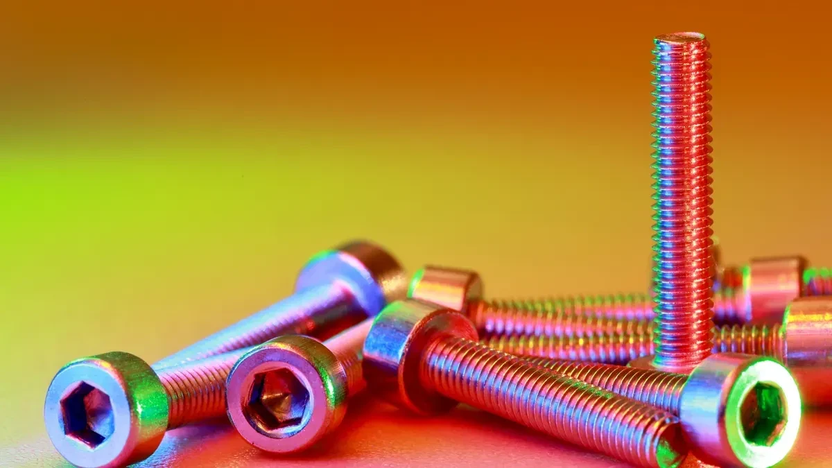
Megawatts BlogThe Danger of Reusing Hardware: Why New Fasteners Are Critical for Cylinder Head RebuildsA successful engine rebuild hinges on one crucial detail: precise clamping force. Reusing old cylinder head fasteners—especially stretched bolts and deformed washers—is a direct ticket to...
BLOG
Megawatts BlogThe Danger of Reusing Hardware: Why New Fasteners Are Critical for Cylinder Head RebuildsA successful engine rebuild hinges on one crucial detail: precise clamping force. Reusing old cylinder head fasteners—especially stretched bolts and deformed washers—is a direct ticket to... -
 BLOG
Megawatts BlogEngine Compression Loss and Misfires: Signs You Need Valve Guide ReplacementWhen a heavy-duty diesel engine experiences unexplained misfires or a sudden drop in compression, the root cause is often hidden deep within the cylinder head. Worn valve guides are silent culprits th...
BLOG
Megawatts BlogEngine Compression Loss and Misfires: Signs You Need Valve Guide ReplacementWhen a heavy-duty diesel engine experiences unexplained misfires or a sudden drop in compression, the root cause is often hidden deep within the cylinder head. Worn valve guides are silent culprits th... -
 BLOG
Megawatts BlogEngine Blow-By Explained: When to Invest in New Cylinder Liner and Piston KitsCylinder liner and piston kit replacement becomes essential when engine blow-by leads to loss of compression or excessive oil consumption. Reliable parts are vital for generator sets and construction...
BLOG
Megawatts BlogEngine Blow-By Explained: When to Invest in New Cylinder Liner and Piston KitsCylinder liner and piston kit replacement becomes essential when engine blow-by leads to loss of compression or excessive oil consumption. Reliable parts are vital for generator sets and construction...

Subscribe to enjoy 10% off
Stay informed about new products and sales

-
INFORMATION
Contact Us
-
CHINA SALES OFFICE: No. 2-11, No. 8, Gaotai Road, Gaishan Investment Zone, Cangshan District, Fuzhou, Fujian
-
SAUDI ARABIA FACTORY: 7264 Shakra, Al Faisaliyyah, REFB3035, 3035, Riyadh 12883
-
COLOMBIA SALES OFFICE: 92-32 26th Street, 03-118, Bogota
-
NIGERIA FACTORY: Plot 5 Chivita Avenue Ajao Estate Isolo Lagos
-
Email:sales@megawattsparts.com
Follow Us


Copyright © 2025 Megawatts All Rights Reserved.
Select Previous Button or Search Directly on Search Bar!
Shop All
 English
Currency: <{ pagedata.current_currency }>(<{ pagedata.current_currency_code }>)
Are you in the right place?

You agree to MegaWatts.com's Terms of Use and Privacy Policy by subscribing. You may receive emails with useful tips, promotions, and offerings.
No, thanks. I'd rather pay full price.