







































Diesel Generator Won't Crank: A Step-by-Step Electrical Diagnostic Checklist for Mechanics
by Megawatts - Updated At 2026-09-24
When a diesel generator won't crank, check the electrical system first. Do not chase fuel or mechanical theories yet. Low battery voltage and corroded connections cause most no-start condition calls. A battery may crank the engine but fail to power the ECU or fuel solenoid. Load testing matters. This five-step electrical diagnostic checklist covers parasitic draws, neutral safety switch faults, and control panel logic lockups. These troubleshooting steps help isolate the fault fast, minimize downtime, and show when to escalate. Whether it is a prime power unit or a standby system, most diesel generators share similar starting failures. Common starting issues trace back to voltage or connections. Document every reading.
Step 1: Battery Voltage And Connections
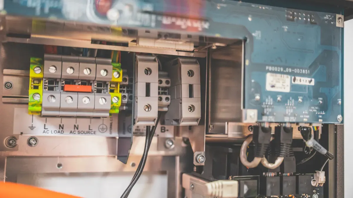
Measure Resting And Cranking Voltage
Battery voltage and connections form the foundation of every diagnostic routine. A diesel generator won't crank for many reasons, yet a weak battery sits at the top of the list. Set the digital multimeter to DC volts and measure across the battery terminals with all loads off. A healthy 12V battery at rest shows its proper nominal voltage. Cranking voltage must remain sufficiently high to support the starter circuit, and a drop that consistently prevents starter engagement indicates a weak battery. Reliable engagement disappears below that threshold.
A 24V bank behaves differently. Float voltage while idle typically runs between 26.8V and 27.6V, and a drop to 18V–20V during cranking is normal. Insufficient cold cranking amps push the dip below 16V, and a DSE 8610 MKII controller then triggers a Low Battery Voltage or Cranking Failure alarm. This electrical signature confirms the battery cannot support the starter circuit.
Resting voltage alone can mislead. A battery may crank the engine yet fail to power the ECU, fuel solenoid, or sensors. Test under load, not just at rest. This troubleshooting step separates a surface charge from real capacity.
Clean, Tighten, And Load-Test Terminals
Corroded or loose electrical connections add resistance and mimic a failed battery. Inspect both terminals, the ground strap, and the frame bond. Clean every contact to bright metal, then tighten each fastener to a snug fit. Apply a protective coating afterward.
Warning: Batteries release hydrogen gas, which is explosive. Wear eye protection and gloves, and keep sparks, flames, and smoking materials away. Battery acid burns skin and eyes, so flush any contact with water immediately.
Load-test the battery with a conductance tester or carbon pile. Compare the result against the rated cold cranking amps. Standby diesel generators often sit idle for long periods, allowing sulfation to quietly reduce battery capacity. Document every voltage reading during this troubleshooting sequence. These numbers guide the remaining diagnostic steps and speed future repairs.
Step 2: E-Stop, Neutral Safety Switch, And Panel Logic
Test E-Stop And Neutral Safety Switch Continuity
A faulty emergency stop or neutral safety switch ranks among the most common electrical problems that block cranking. These safety devices interrupt the start circuit intentionally. When they fail, the interruption becomes permanent. Set the multimeter to continuity or resistance mode and isolate each switch from the circuit. A closed E-stop should read near zero ohms. An open reading indicates a failed contact or broken wire. Test the neutral safety switch the same way. This switch prevents cranking while the transmission sits in gear. Resistance above a few ohms signals internal corrosion or pitting. Replace any switch that fails these checks.
No-start scenarios frequently trace to faulty safety interlocks. A corroded switch or loose connection easily breaks the circuit path. Outdoor and enclosed diesel generators in particular suffer from moisture intrusion at these connections.
Reset A Frozen Or Fault-Coded Controller
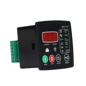
Controller alarms often point directly to the failed circuit. Read every fault code before clearing it. A Low Battery Voltage or Cranking Failure alarm confirms the battery cannot support the starting circuit. A frozen panel requires a systematic reset.
- Perform a hard power cycle: fully de-energize the system, disconnect the battery, wait 5-10 minutes, then reconnect and restore power.
- Check all generator and main panel breakers; reset if needed.
- Inspect and ohm fuses; replace only with identical ratings.
- Verify battery health and clean or tighten battery connections.
- Open the panel with power off: reseat ribbon cables and look for moisture, corrosion, or chewed wires.
- Check for proper grounding, since a poor ground connection causes erratic behavior.
- Measure input voltage to the control panel; it should match specifications, typically 12V or 24V DC.
- Look for burnt components or discolored areas on the circuit board indicating overheating.
If these troubleshooting steps do not resolve the fault, call a professional. Document every reading during this diagnostic phase.
Step 3: Starting Circuit, Relay, And Solenoid
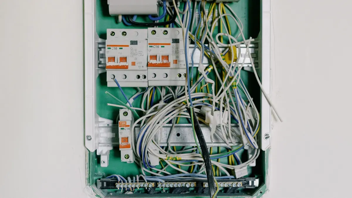
Trace Continuity And Voltage Drop
The starting circuit must deliver full current from the battery through the ignition switch, relay, and solenoid to the starting unit. High resistance anywhere in this path mimics a failed component. Set the multimeter to resistance mode. Test from the power source positive terminal to the ignition switch input. Then test from the switch output to the relay coil input. Continue through the solenoid trigger wire. Every connection should show near zero ohms.
A voltage drop test reveals hidden resistance under load. This diagnostic method finds high-current circuit faults. Clip one meter lead to the power source positive. Crank the engine for four to five seconds. Move the second lead along the circuit path. Expect under 50 millivolts at each point: the solenoid connector, keyswitch input, keyswitch output, and safety switch terminals. Readings above 50 mV indicate corrosion or a loose terminal. The acceptable total drop across the positive cable is 0.2 to 0.5 V. Test the ground side: black probe on the engine block, red probe on the power source negative. A drop above 0.2 V indicates a bad ground connection. This troubleshooting approach isolates resistance without guessing.
Interpret The Solenoid Click And Relay
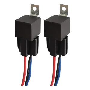
A single solid click means the solenoid engaged but the starter did not rotate. This points to a faulty starter motor. Measure voltage at the component's main stud during cranking. If full power arrives but the motor stays silent, the component requires replacement.
Rapid clicking indicates the solenoid engages and drops out repeatedly. The power supply voltage collapses under load. Perform a load test. A healthy unit should deliver at least 9.6 V under load. Readings below that confirm the power supply needs replacement. This pattern is common when a system sits idle for long periods.
Document every reading during this electrical system check. These numbers guide the remaining steps. The same circuit path applies to almost all industrial generator units. A faulty neutral safety switch or corroded control panel connection produces identical symptoms.
A diesel generator won't crank diagnosis requires patience. Follow these electrical troubleshooting steps in order.
Step 4: Parasitic Draws And Starter Test
Isolate Parasitic Draws That Drain The Battery
A parasitic draw drains the battery while the generator sits idle. This fault leaves the unit unable to crank when called upon. Set the multimeter to DC amps and connect it in series with the negative battery cable. A clamp meter offers a safer alternative because it measures current without breaking the circuit. Wait for all modules to enter sleep mode before recording the reading. A healthy diesel generator typically draws very little current when idle. Readings above that low threshold indicate a parasitic load. Pull fuses one at a time to isolate the offending circuit. This diagnostic step protects the battery and the starting circuit.
Bench-Test Or Bypass The Starter Safely
Slow cranking often indicates excessive resistance in the electrical system rather than a failed starter motor. Perform a direct bypass test to confirm. This procedure is a temporary emergency fix only.
- Prepare insulated gloves, a screwdriver or wrench, and a starter cable.
- Locate the starter relay or solenoid on the starter motor or transmission housing.
- Verify that the battery connections are secure.
- Identify the power terminal and the starter terminal on the solenoid.
- While wearing insulated gloves, connect the power terminal to the starter terminal with the starter cable.
- Attempt to start the unit. If it starts, the solenoid is faulty. If it does not, the issue lies with the starter motor or the battery.
Warning: This bypass transfers full current directly. High voltage and rotating parts pose serious injury risks. Wear insulated gloves and keep hands clear of the cranking assembly.
A bench test isolates the starter motor from the circuit. Apply the rated voltage and observe cranking speed. Different generator enclosures may require different access procedures, but the electrical test remains the same. Document every reading during this troubleshooting phase.
Step 5: Mechanical Conditions, Interlocks, And Fuel
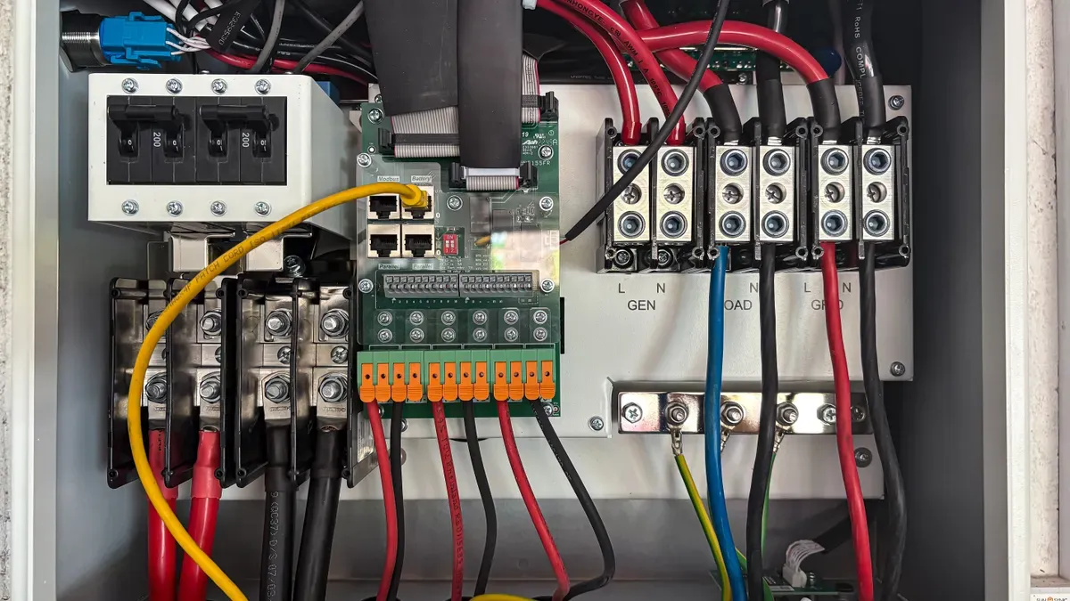
Check Cranking Speed, Seizure, And Interlocks
Cranking speed reveals whether the electrical system delivers enough power to spin the engine. A diesel engine requires sufficient rotation to build compression heat. Watch the tachometer or listen to the rhythm during engagement.
Most diesel engines need to be rotated between approximately 150 to 250 RPM before they start, with some technical sources citing a wider range of 100 to 300 RPM. Starting below 100 RPM is generally unlikely to achieve compression ignition.
Slow, labored cranking points to excessive resistance in cables or a weak battery. A seized accessory, locked water pump, or failed bearing stops rotation entirely. Disconnect the belt and retry if seizure is suspected.
Modern controllers also block cranking through safety interlocks. These latched faults prevent starter engagement until cleared at the panel.
|
Safety Interlock |
Trigger Condition |
Effect on Cranking |
|
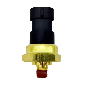
Low oil pressure |
Oil pressure drops below threshold |
Controller locks out the starter until fault is cleared at the panel |
|
High coolant temperature |
Coolant temperature exceeds safe limit |
Starter is prevented from engaging until the fault is reset |
|
Overspeed fault |
Engine speed exceeds rated limit (latched fault) |
Starter lockout remains active until cleared at the control panel |
|
Safety lockout (general) |
Any latched safety shutdown |
Listed as a cause of "won't crank / no start" in the diagnostic matrix |
Verify Fuel Solenoid, Air Bleeding, And Preheat
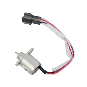
The fuel solenoid must energize during cranking to open fuel flow. Listen for an audible click at the injection pump. No click indicates an electrical fault in the solenoid circuit or a control panel logic issue.
Air trapped in fuel lines creates a no-start condition even when the engine cranks normally. Bleed the system methodically:
- Gather tools: wrench set, bleeder screw key, clean rags, safety goggles, and diesel fuel.
- Locate the fuel tank, lines, filter, and injectors before starting.
- Ensure the engine is off and the key is removed.
- Check the fuel filter for a built-in bleeder screw.
- Place a rag beneath the screw, loosen it counterclockwise, and allow air-fuel mixture to escape until only bubble-free fuel flows.
Trace the fuel path from tank to injectors. Start bleeding at the lowest point, usually the filter housing or water separator. Loosen the bleed screw 1–2 turns, then operate the manual lift pump until bubble-free fuel flows. Tighten the screw while fuel still flows. Bleed at the injectors last, working from farthest to closest.
Glow plugs or preheat systems assist cold starting. Test voltage at the glow plug bus during preheat. Finally, inspect the governor and fuel delivery linkage for binding or disconnected rods. These mechanical checks complete the diagnostic sequence for starting failures.
When To Stop And Call A Professional
Red Flags And High-Voltage Risks
Some faults exceed the scope of field diagnostics. Internal engine damage, repeated protective shutdowns, and unexplained overheating demand professional attention. Low oil pressure combined with abnormal engine noise points to oil pump failure, bearing wear, or lubrication-system damage. Knocking, rattling, or grinding sounds indicate worn or damaged internal components. Blue smoke suggests worn seals or piston rings. White smoke points to coolant leaks or fuel system issues. These symptoms require a qualified technician, not further troubleshooting at the worksite.
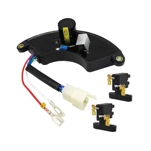
High-voltage circuits present serious hazards. Alternator and automatic voltage regulator (AVR) diagnosis, live electrical measurements, automatic transfer switch internal repairs, and emissions-system faults all carry electrocution risk.Do not attempt these repairs without proper training and equipment. Any generator with persistent faults after electrical checks also warrants professional service. When unusual sounds or vibrations continue, schedule an inspection so a qualified technician can diagnose the source and recommend repairs or an overhaul.
Related Reading: Learn how a faulty AVR destroys your electronics before attempting any complex voltage diagnostics."
Preventative Maintenance And Parts Sourcing
Scheduled maintenance prevents most no-crank failures. Perform battery load tests at regular intervals. Clean and tighten terminals during every service visit. Check controller fault logs and test safety interlocks. These steps keep the starting circuit reliable.
Follow the five-step sequence as a repeatable field routine. Start with battery voltage and connections. Move to switches and panel logic. Trace the starting circuit and solenoid next. Then check parasitic draws and test the starter. Finish with mechanical, interlock, and fuel checks. Most diesel generator won't crank faults trace back to voltage, connections, or a safety logic interruption, not the starter itself. Document every voltage and resistance reading during troubleshooting. This practice speeds future diagnostics on any generator unit. Scheduled battery load tests, terminal cleaning, and control panel checks keep cranking reliable. Reliable aftermarket parts from suppliers like Megawatts Parts help avoid repeat downtime.
FAQ
What voltage range indicates a battery problem?
A resting voltage well below the nominal value for a healthy battery, or a cranking voltage that drops too low, signals a weak battery. A drop that reliably prevents starter engagement indicates the battery cannot support the starting circuit.
Why does the neutral safety switch cause starting failures?
The neutral safety switch interrupts the start circuit when faulty. Moisture corrodes connections in exposed or outdoor generators, making this a common failure point. Continuity testing confirms functionality.
What does rapid clicking from the solenoid mean?
Rapid clicking indicates the solenoid engages and drops out repeatedly. The voltage collapses under load. A load test below 9.6V confirms replacement is needed.
How do you isolate a parasitic draw?
Connect the multimeter in series with the negative cable. Wait for all modules to enter sleep mode. A reading above the typical minimal current draw indicates a parasitic load. Pull fuses individually to locate the circuit.
When should diagnostics stop and a professional take over?
Stop when you encounter internal engine damage sounds, high-voltage circuits, or repeated protective shutdowns. A qualified technician with proper training must handle these risks.
Read More
-
 BLOG
BLOG Megawatts BlogMagnetic Coil Degradation: Why Your Diesel Engine Stop Solenoid Fails Under Extreme HeatExtreme heat is the primary enemy of a diesel engine stop solenoid. The heat breaks down the electrical insulation inside the magnetic coil. This degradation raises resistance and creates short circui...
 -
 BLOG
Megawatts BlogThe Hidden Cost of Expired Inventory: Shelf Life and Proper Storage of Rubber Gasket Seal KitsA gasket seal kit sits untouched for five years. You paid for it. Now you pay to dispose of it. When a failure occurs, you pay a premium for emergency replacement. These hidden costs accumulate silent...
BLOG
Megawatts BlogThe Hidden Cost of Expired Inventory: Shelf Life and Proper Storage of Rubber Gasket Seal KitsA gasket seal kit sits untouched for five years. You paid for it. Now you pay to dispose of it. When a failure occurs, you pay a premium for emergency replacement. These hidden costs accumulate silent... -
 BLOG
Megawatts BlogCombating Diesel Bug: How Your Fuel Water Separator Filter Prevents Sludge and Microbial GrowthHave you noticed your engine struggling to start, fuel filters clogging more often, or dark sludge in the fuel system? These symptoms indicate diesel bug—microbial contamination that thrives on...
BLOG
Megawatts BlogCombating Diesel Bug: How Your Fuel Water Separator Filter Prevents Sludge and Microbial GrowthHave you noticed your engine struggling to start, fuel filters clogging more often, or dark sludge in the fuel system? These symptoms indicate diesel bug—microbial contamination that thrives on... -
 BLOG
Megawatts BlogComplete Water Pump Assemblies vs. Pressing Bearings: The Most Cost-Effective Repair StrategyFor most drivers and equipment operators, complete water pump assemblies are the most cost-effective repair for the engine's cooling system. When deciding between a full water pump replacement or pres...
BLOG
Megawatts BlogComplete Water Pump Assemblies vs. Pressing Bearings: The Most Cost-Effective Repair StrategyFor most drivers and equipment operators, complete water pump assemblies are the most cost-effective repair for the engine's cooling system. When deciding between a full water pump replacement or pres...
Subscribe to enjoy 10% off
Stay informed about new products and sales

-
INFORMATION
Contact Us
-
CHINA SALES OFFICE: No. 2-11, No. 8, Gaotai Road, Gaishan Investment Zone, Cangshan District, Fuzhou, Fujian
-
SAUDI ARABIA FACTORY: 7264 Shakra, Al Faisaliyyah, REFB3035, 3035, Riyadh 12883
-
COLOMBIA SALES OFFICE: 92-32 26th Street, 03-118, Bogota
-
NIGERIA FACTORY: Plot 5 Chivita Avenue Ajao Estate Isolo Lagos
-
Email:sales@megawattsparts.com
Follow Us


Copyright © 2025 Megawatts All Rights Reserved.



Select Previous Button or Search Directly on Search Bar!
Shop All
 English
Currency: <{ pagedata.current_currency }>(<{ pagedata.current_currency_code }>)
Are you in the right place?

You agree to MegaWatts.com's Terms of Use and Privacy Policy by subscribing. You may receive emails with useful tips, promotions, and offerings.
No, thanks. I'd rather pay full price.